Breadboarding a Whistle Synth |
April 26th, 2024 |
| music, tech, whistling |
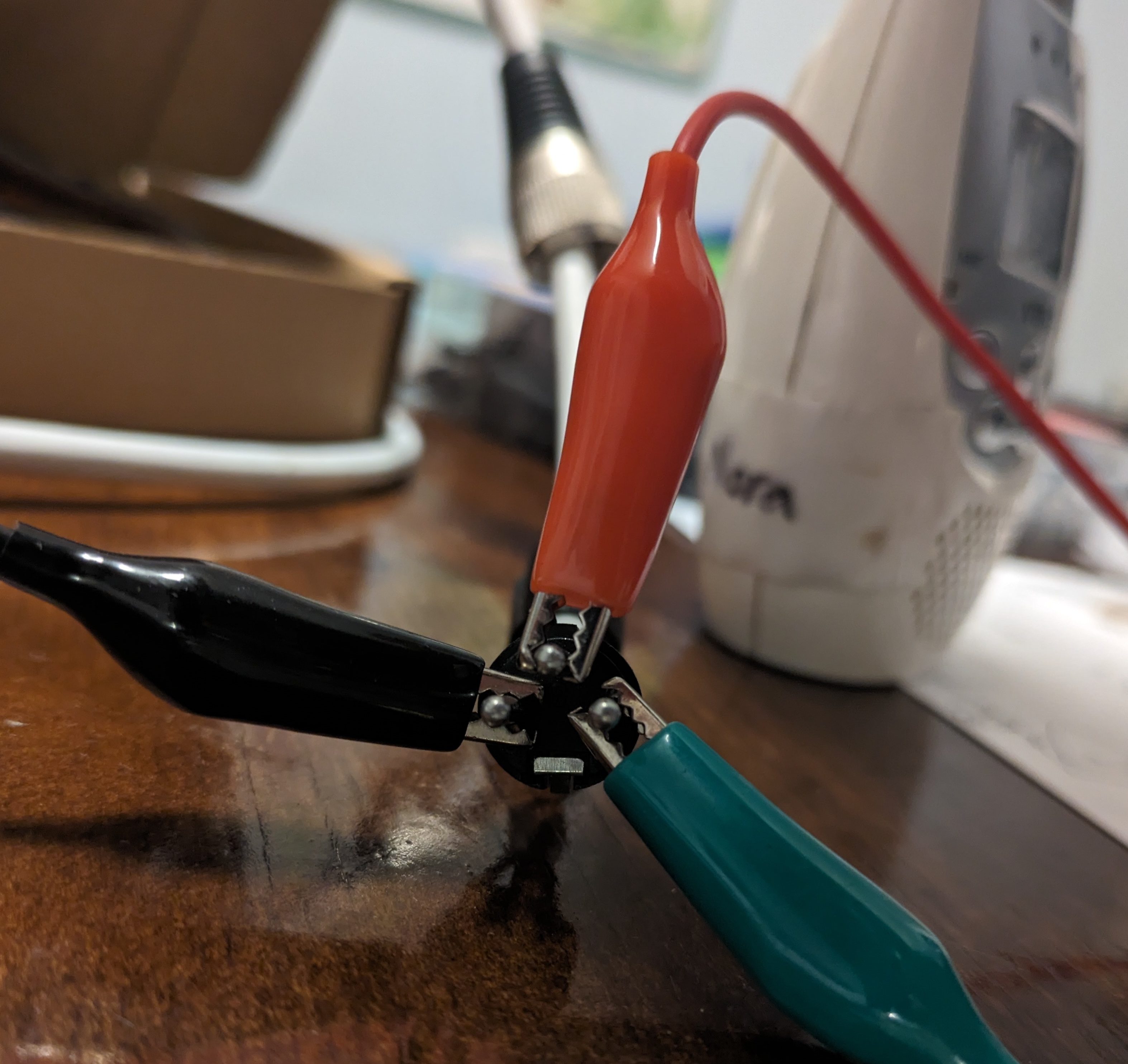
Yesterday I got started on the first component: getting audio into the microcontroller. I want to start with a standard dynamic mic, so I can keep using the same mic for talkbox and whistle synth, so it should take standard balanced audio on XLR as input. In a full version this would need an XLR port, but for now I can pull back the housing on an XLR cable:
I'm planning to use the Teensy again, which will be lowest noise at 3.3v peak-to-peak. What is the mic giving me? Whistling as loudly as I can into my e835 dynamic mic I see 23mV peak-to-peak:
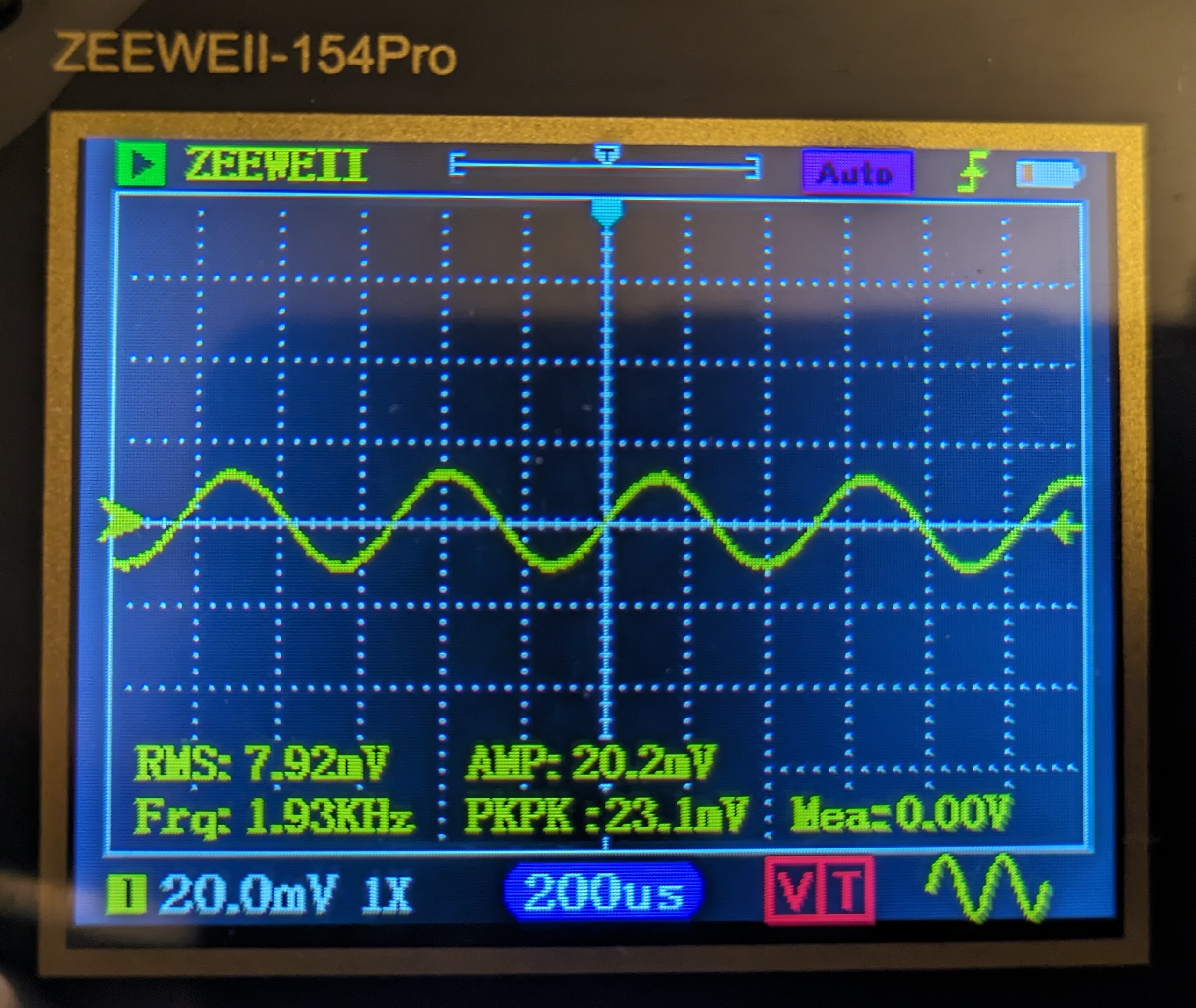
This means I need to amplify it by ~150x: 3.3v/23mV.
I found these notes from MAS 836 pretty helpful, and sketched out an ac-coupled differential amplifier, with a voltage divider to bias it up to a mean voltage of +1.65v and the same protective diode arrangement I used on my pluck sensor to keep from going above +3.3v or below 0v:
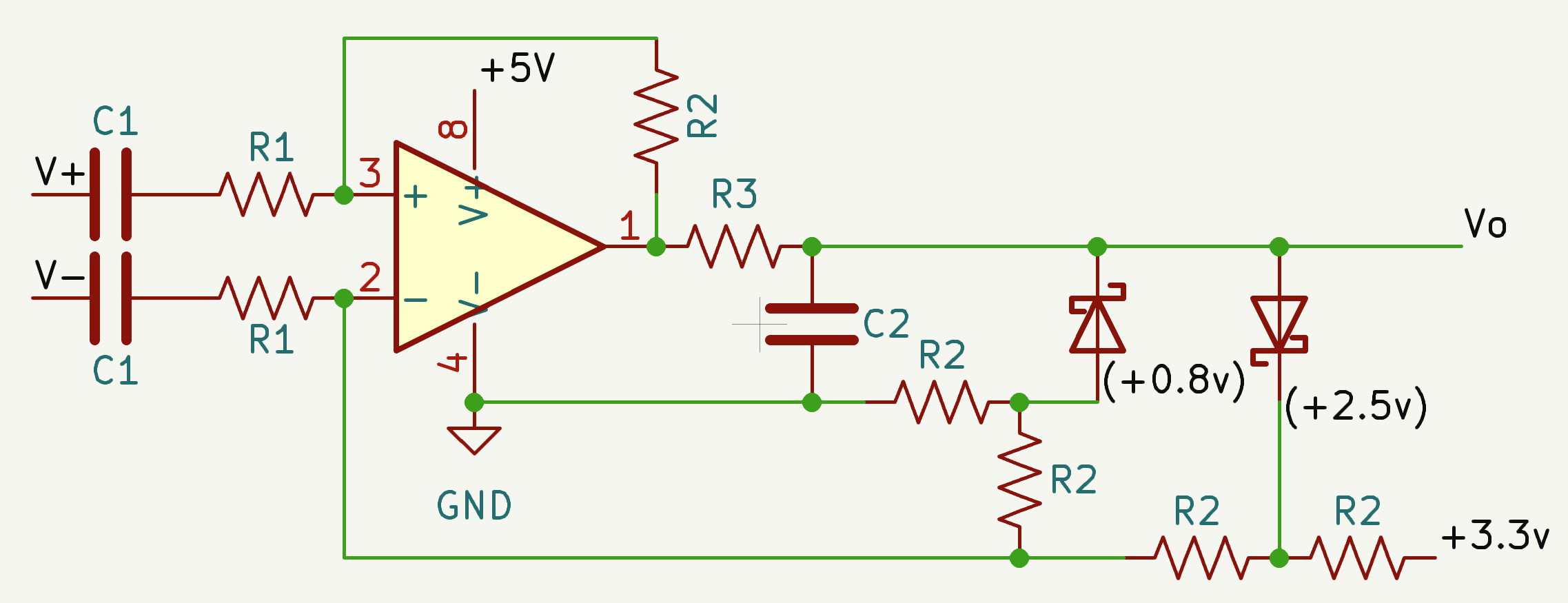
It also includes simple high-pass and a low-pass filters.
For choosing the component values, I set R1 to 33Ω because my understanding is standard dynamic mics want a low input impedance. Then I set R2 to 5.1kΩ (155x) because gain is R2/R1 and this gives us close to the target gain I calculated above. The frequency cutoff of the high-pass filter on the input is 1/(2 * pi * R1 * C1), and I'd like this to be 500Hz (or a bit lower) because that's the lowest I can whistle. Since we've already chosen R1, this means C1 should be 9.6µF; I used 10µF. For the low-pass filter I'd like the frequency cutoff to be 2.5kHz (or a bit higher), the upper end of my whistling range, and it should be 1/(2 * pi * R3 * C2). We haven't picked either of these, but I think we want R3 to be low so we don't make a lot of heat, so I did 7.5Ω. This means C2 should be 8.4µF, but I didn't have one so I used a 4.7µF and 3.3µF in series for a total of 8µF. Note that for C1 I rounded up and for C2 I rounded down, so that this wouldn't cut off any of my whistling range.
For the amplifier I wasn't sure what to use. I want something with reasonable audio performance, but it doesn't need to be super high-quality because the output is just going to be interpreted for (a) zero-crossing detection and (b) overall volume. I decided to go with the LM358P because they're cheap. For the diodes I used the same 1N5818 schottkies I used last time.
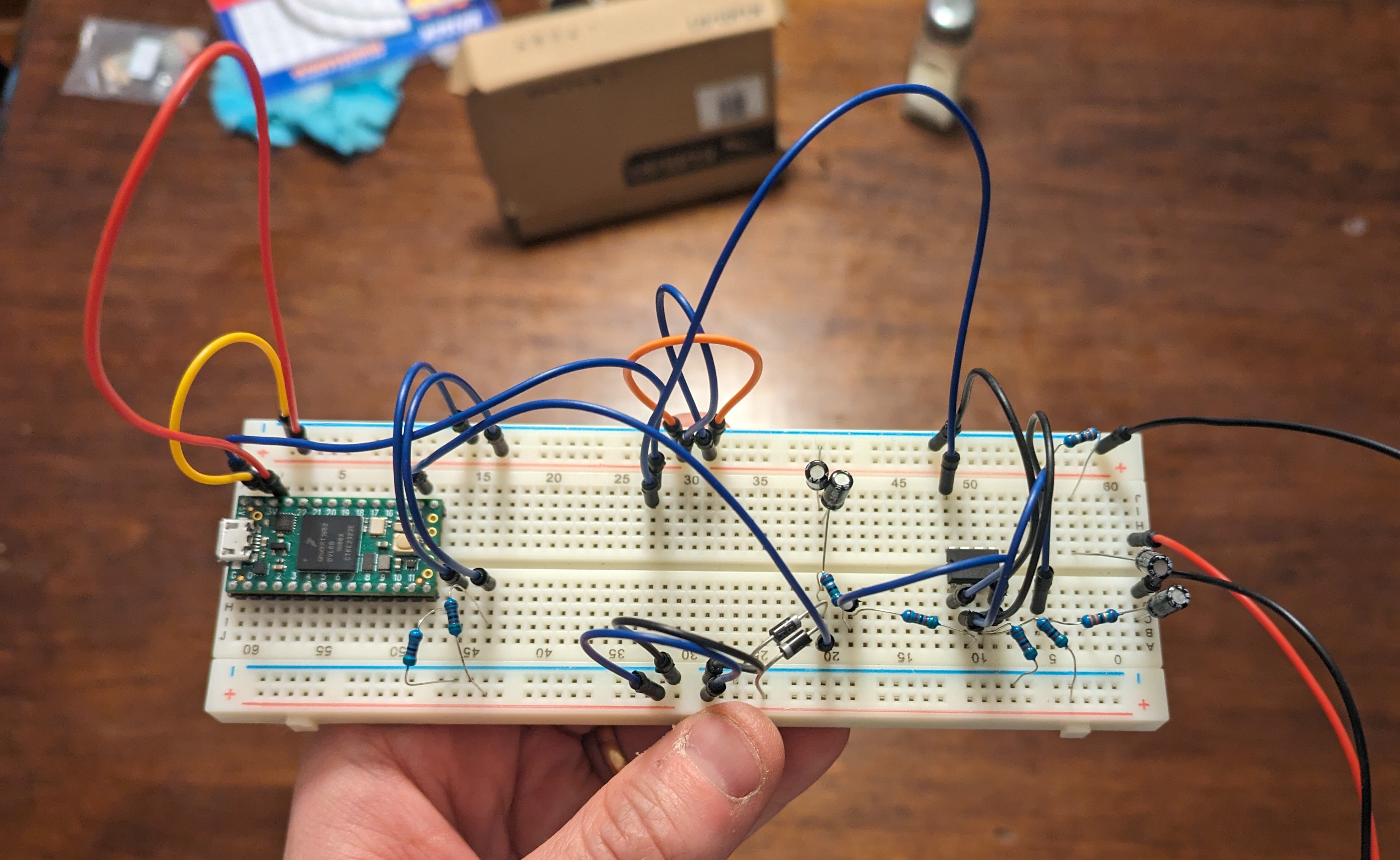
I breadboarded it up:
Testing it with the oscilloscope it looks good enough:
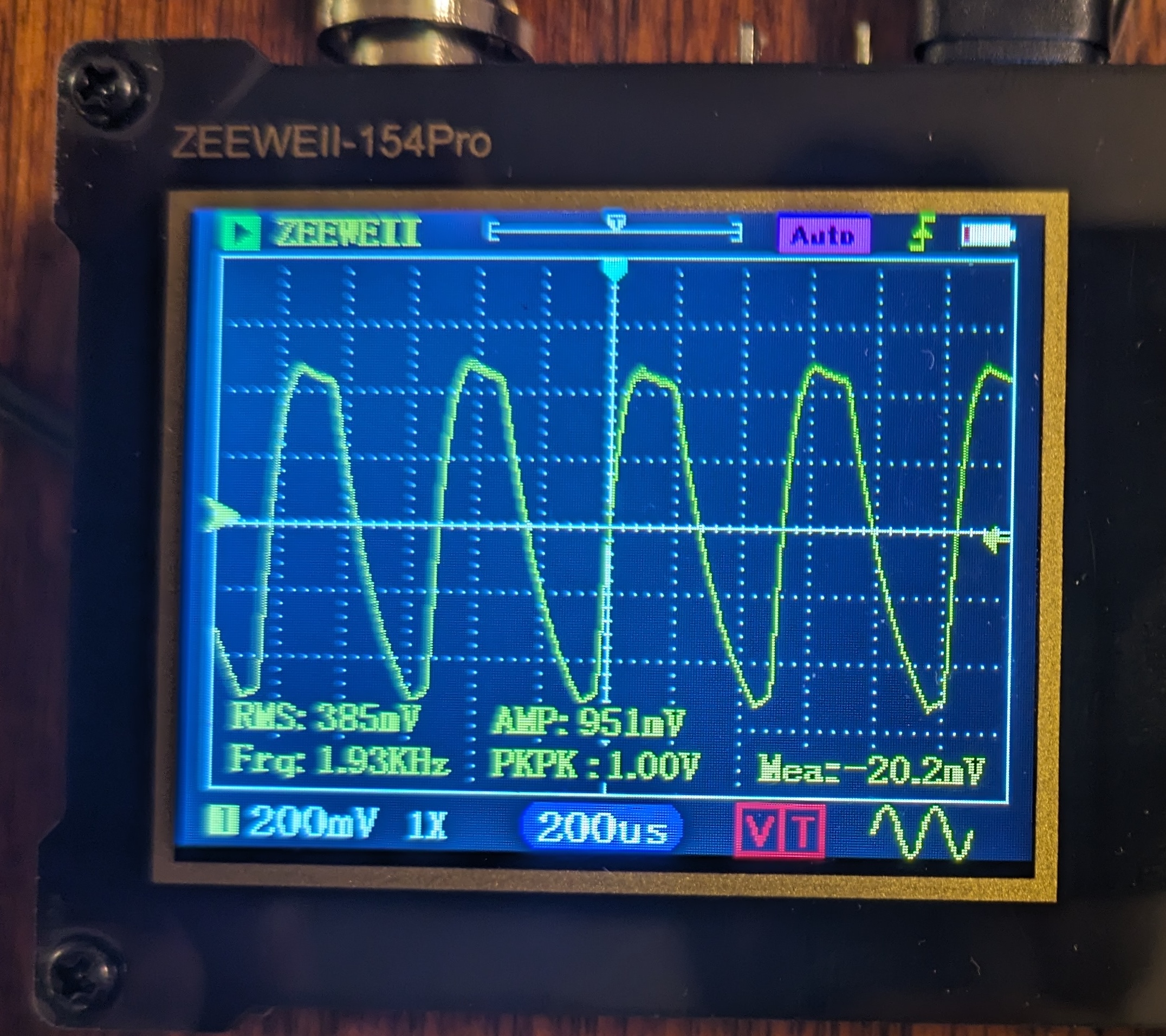
That curve is clearly not symmetric, so I don't think this would make a good mic pre-amp for listening to music regularly, but it doesn't look noisy and should be enough for my purposes.
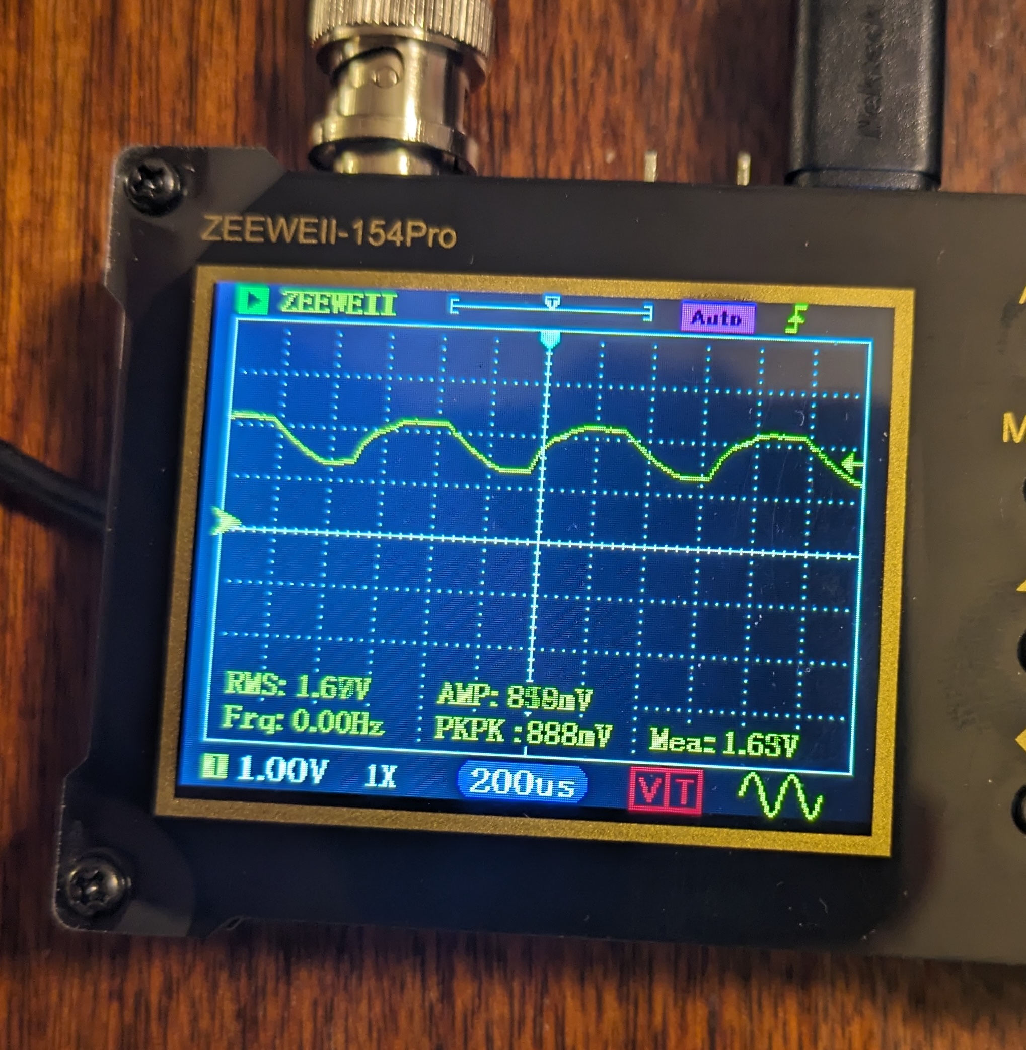
To verify the biasing was working correctly I switched my oscilloscope to DC mode, and I do see it centered on +1.63v, which is close enough to +1.65v:
Next steps:
Port my pitch detection and synthesis code to the Teensy.
Add potentiometers so I can tweak synth params in real time.
Add a DAC so it can produce output independently. I'm planning to use this PCM5102 I2S.
[1] Focusrite 2i2 for ADC and DAC, Raspberry Pi for processing, numpad
for control.
Comment via: facebook, lesswrong, mastodon, substack